I managed to "finish" the build yesterday.
- I found a better screw for the transformer :
- I also replaced the standoffs by an assembly of nuts / washers to lower the level of the PSU board, as suggested by Wave on the groupDIY forum :
- I mounted the heatsinks
- Wiring XLR / Jacks
- Wiring the transformer
I used the BOM suggested transformer. Here are the infos :
So for 230V I had to tie Gray to Violet :
Then I heated the shrink-tube to cover the wires.
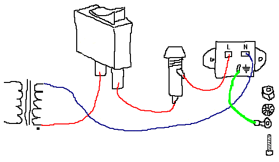
I found this schema on the forum which explain how transformer / fuse / IEC should be connected :
Even the position on the switch is important. As it is, the live will only be present in the rack when the switch is engaged. If they were reversed, it would come to the switch in all cases.
In my case Live is Blue and Neutral is brown.
BEWARE : On following pictures I've just noticed that I DID exchange the position on the Power Switch, so please not it's correct.
- Some switches wiring (As explained later, the NKK switches seem to be correct, but not sure about the I/O L/R ones).
- Aaaaaaand everything wired (except PSU board to Main board and the chips that I added after checking PSU voltages). Please not the fact that I disconnect from the PSU side, not the other, in order to avoid having voltage through the disconnected wires.
- Don't forget to put the fuse or it won't work that great :) And DON'T FORGET TO PUT EVERY GROUND WIRES ON THE GROUND STAR BEFORE ADDING IEC Cord !!
- My voltages were ok for +-12, but I only got -12 and +12 values for +-15 points. So I adjusted with the trim pots (strange though I had so low voltages as I pre-trimmed them to 1K33 as advised) to obtain +-15.
I then connected PSU board to Main board (disconnected control board). Again, all voltages were correct and stable, and VUMeter did light up in blue. I added the control board, and again the voltages were correct.
My Push button for Stereo/Mono Sidechain was not working properly, but it was due to the fact I did not screw its wire in the connector properly.
Unit passed audio on both channel. I was able to take step 2 (Unity gain) of Calibration correctly (even when Compressor In I have some distortion). But I'm stuck at Step 3, as I can't adjust TP12 to read the same as TP10. With the pot fully trimmed, I still got lower value than TP10. I have to find out why it is so. Both channels don't react the same, so something must have gone wrong during component implant or soldering on one of the channels.
Also at this step I noticed I might have wired Ext In switch the wrong way (In seems to be on the down). Maybe all those 3 switches are wrong, I'll see when I'll be there.
I'll let you know when I'll go further !!


Aucun commentaire:
Enregistrer un commentaire